
Setting PID triggers allows you to configure the diagnostic tool to automatically save PID data to a file, when a PID value meets an upper/lower limit (trigger point).
When a PID value meets the trigger point it activates the trigger which captures a short recording of all available PID data and saves it as a data file.
You can review the saved data file to closely evaluate not only the PID that triggered the event, but all the PIDs being monitored to collectively see what was happening at the time of the event.
Examples of the following trigger states (Armed / Not Activated - upper image) and (Activated - lower image) are shown below.
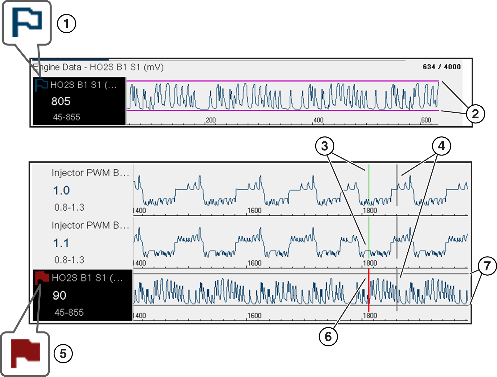
| 1. | Armed PID Trigger Indicator - A blue outlined flag indicates the PID trigger is armed. |
| 2. | Upper and Lower Limit Lines (Armed) - Colored limit lines indicate the trigger is armed but not activated. |
| 3. | Trigger Activation Point Reference Cursor - Green cursors lines are displayed on all the other PID graphs to indicate their relationship to where the trigger occurred. |
| 4. | Pause Cursor - A vertical gray cursor line is displayed (all PIDs) as a marker in the where the data was paused and the file was saved. |
| 5. | Activated PID Trigger Indicator - A red flag indicates the PID trigger has activated. |
| 6. | Trigger Activation Point Cursor - A red cursor line is displayed in the PID data where the trigger was activated. |
| 7. | Upper and Lower Limit Lines (Not Armed and Activated) - Gray limit lines are displayed when the trigger is armed but not activated and after the trigger has been activated. |
The icons (below) are used to help you quickly identify the status of individual PID triggers:
|
Icon |
Description |
|
|
Trigger Armed |
|
Trigger has been set (configured) and is armed. |
|
Trigger Activated |
|
Trigger has been activated (upper or lower limit has been met). |


To use triggers, they must be turned on (set/configured), and then armed. Use the following procedures to setup PID triggers.
| 1. | Highlight the PID to setup with a trigger. |
| 2. | Select the Trigger icon. |
Selecting the Trigger icon displays trigger menu options:
| - | Set Trigger—opens setup screen for upper/lower limits (trigger points) |
| - | Arm Trigger—arms the trigger to capture data |
| - | Clear All Triggers—deletes all previously set triggers |
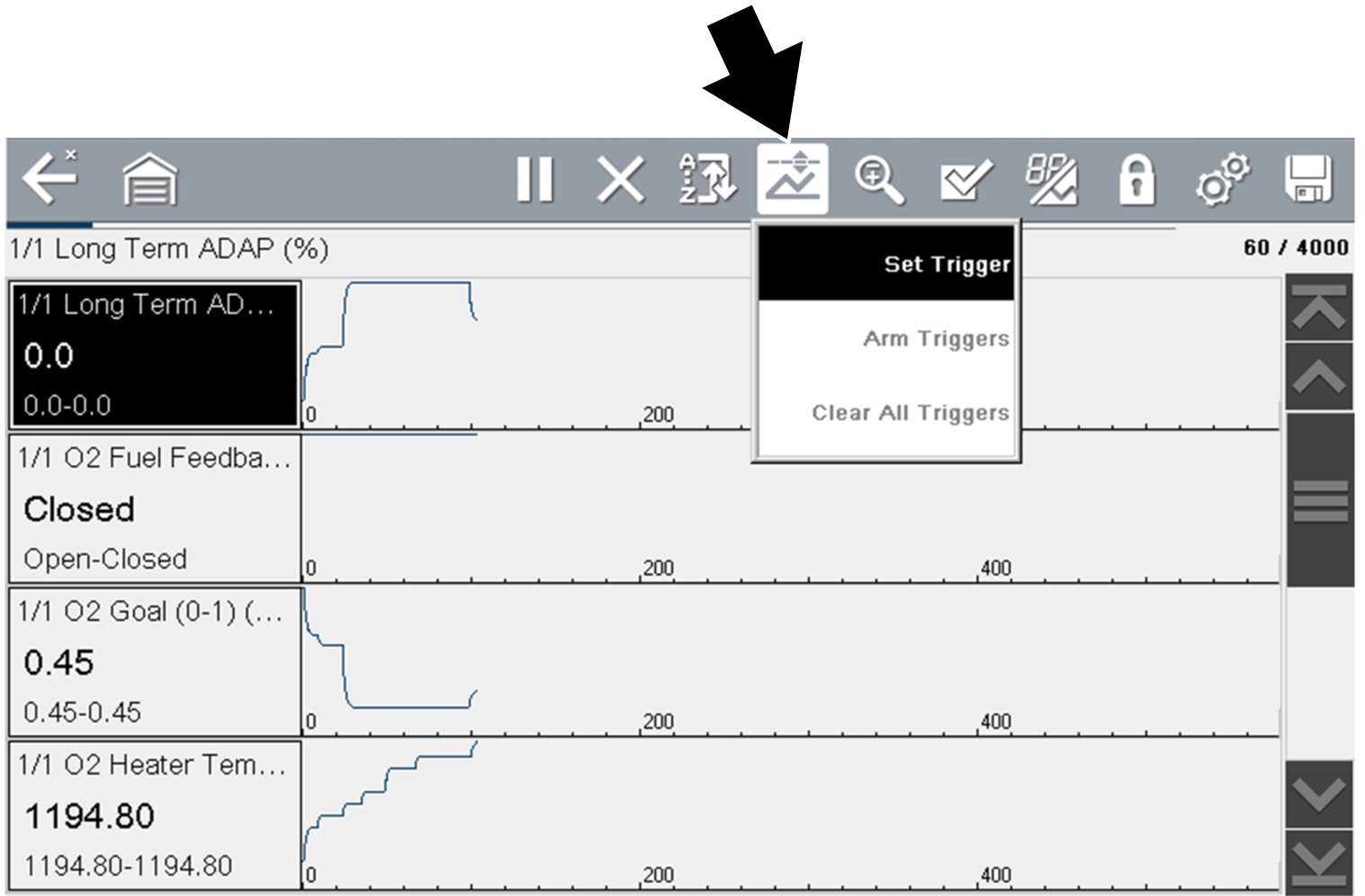
Trigger menu
If triggers are already set, the menu options are:
| - | Clear Trigger—deletes the highlighted trigger |
| - | Disarm Trigger—disarms the highlighted trigger |
| - | Clear All Triggers—deletes all set triggers |
| 3. | Select Set Trigger. |
A graph of the highlighted PID and setup icons display.
The upper trigger point must be set first. A red horizontal line is displayed across the data graph representing the upper trigger point.
| 4. | Use the plus (+) and minus (–) icons, or the up b and down d arrow buttons to change the position of the upper trigger point. |
| 5. | Select a, to set the upper trigger point. |

The upper trigger line changes color to gray and the lower trigger line displays in red.
| 6. | Change the position of the lower trigger line in the same manner as the upper. |
| 7. | When finished, select a, to set the lower trigger level. |

Trigger setup - lower limit
The display returns to the PID data view and the trigger points appear as horizontal lines across the designated graph. Repeat this procedure to establish trigger points for other parameters (up to three) if desired.
Only three parameters can have trigger levels set at one time, but only one of the conditions needs to be satisfied for triggering to occur.

Trigger set (not armed)
| 1. | Select the Trigger icon. |
| 2. | Select Arm Triggers. |
The trigger point lines change color to indicate an armed condition.
All set PID triggers are armed simultaneously (if more that one is set). Once armed it remains armed until you clear it or the trigger is activated.

Trigger armed
A trigger is activated (displays red flag)  when a PID value meets an upper/lower limit (trigger point).
When a trigger is activated:
| ● | Data collection is briefly paused as the Scanner captures a recording of all available PID data, and saves it as a data file. |
| ● | A gray cursor line is displayed to indicate the point at which the data was paused or saved. |
| ● | An audible alarm is sounded |
| ● | A message displays indicating a data file was saved. |
| ● | Data collection continues. |
| ● | The activated PID trigger is disarmed. Note - if a different PID trigger is activated subsequently, an additional data file will be recorded. |
| ● | A red cursor line is displayed on the graph of the PID with the activated trigger to indicate where the trigger occurred. |
| ● | A green cursor line is displayed on all the other PID graphs to indicate their relationship to where the trigger occurred. |

Trigger activated